Station Properties
Selecting a station displays the properties for that station in the Property Editor. Depending on the station type, different properties may display.
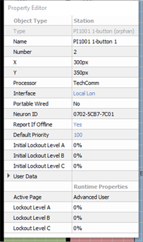
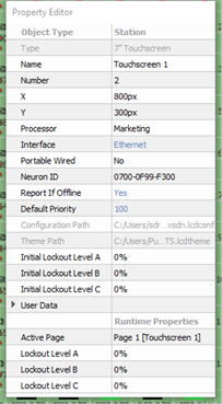
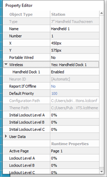
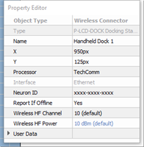
- Type - the type/style of station you have selected. This property is not selectable or editable.
- Name - the name of the station.
- Number - the order in which the station appears in the Browser unless a custom "User Sort" has been specified. This "Number" property can be edited, although you will be notified immediately by dialog if a station number conflict occurs. Follow the dialog to continue.
- X & Y - the location (in cm) of the station in relation to the space it is located.
Note: 0,0 is the top left corner of the space.
- Processor - the Paradigm Processor that the station will connect (bind). This field is a drop-down list of all available processors.
- Interface - the method in which the station either is already connected or is expected to be connected to the Paradigm Processor. This property will be hidden in Basic access mode unless the project includes a Network Station Power Supply P‑NSPS‑D). By default, when a station is initially added into the project, prior to binding to the Processor, the Interface property defaults to "Autodetect". Once the station is bound to the Paradigm Processor, the Interface property will automatically update to reflect the connection type (Ethernet, Local Lon, or the configured NSPS it was bound through). At configuration this property can be assigned using the options available in the drop-down list. When the station is a P‑LCD‑Dock or a 7" Portable Touchscreen, Ethernet will be the only available option.
Note: Stations that are assigned to a connector, such as the UH1RS Portable Connector and the docked P-TS7 Handheld Touchscreen use the Interface property set for the connector they are assigned.
- Portable Wired - sets if the selected station is a portable wired station, allowing it to be connected and disconnected from either the Local Lon or Ethernet bus.
Note: If "Portable" is set to "Yes", you will need to choose which type of connection will be used according to the device.
Select "Yes: Connector List" when the touchscreen will be connected to the station bus through an available portable connector. This selection will display in a sub-property drop-down list of available connectors for selection unless only one portable connected is found in the space, then it will automatically select the available connector. Only connectors in the same space as the portable station are allowed to be enabled for use. There must be at least one portable station connector assigned to each portable station in the configuration.
Select "Yes: Ethernet" when the touchscreen will be connected to the station bus using the Ethernet port on the touchscreen hardware. - Wireless - a property that is displayed only when the selected object is a 7" Handheld Touchscreen station. This provides additional specification of which Wireless Access Station or Docking Station the 7" Handheld Touchscreen station should receive the wireless signal from in the space. When only one wireless device type (Wireless Access Station or Docking Station) is in the space with the Handheld Touchscreen station, the setting will automatically enable for communication. When more than one wireless device type is in the space, the first one added to the space will be enabled for communication. To enable the second device for the selected Handheld Touchscreen station, click the "Disabled" property for that wireless device. The property will change to reflect Enabled. To disable a wireless device, click the "Enabled" property. The station will change to reflect Disabled.
- Wireless HF Channel - a property that is shown for the Paradigm Wireless Access Station and Docking Station only. This property should be set to the same HF channel as the Paradigm Handheld Touchscreen station it will communicate with. By default, this is set to HF 10. Available options include HF Channels 1 through 12.
- Wireless HF Power - a property that is shown for the Paradigm Wireless Access Station and Docking Station only. This property is the power that the wireless accessory is currently using. By default, this is set to 10 dBm. Selection is available for up to 18 dBm. The higher the power, the stronger the wireless signal range will be for the device.
- Neuron ID - the ID of the station's Echelon Neuron. When "xxxx-xxxx-xxxx" is displayed, this means that the Neuron ID has not been stored for the selected station. See Binding Control Stations.
- Report If Offline - a property that when set to "Yes" will send a station offline error message that displays on the system message area of the associated Paradigm ACP when the station is not connected and online. By default this property is set to "Yes" for all stations except stations and touchscreens that are configured for portable connection.
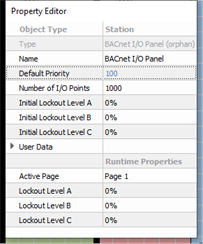
- Default Priority - sets priority level for actions activated at station. The default priority is 100 and the allowable range is 1-200, where 200 is the highest priority. Lower priority control of an object will not operate if a higher priority control for the same object is active. This can be used to designate "more important controls".
- Number of I/O Points - a property that is displayed only for a BACnet I/O Panel. Sets how many configurable points are available for setting in the Property Editor. Up to 1,000 points can be configured.
- Configuration, IR Input - a property that is shown only for compatible ETC Heritage stations. Set to "No" by default, meaning the IR input functionality on the station is disabled. You may set to "Yes" to enable IR input settings.
- Initial Lockout Level A, B, C - set the initial lockout level the station will use for each lockout group upon processor boot or project upload.
- User Data - each object is provided with up to eight User Data Tags that can be used in object identification, such as Folders and Smart Folders filtering and spreadsheet sorts. These are labeled User Data 1, User Data 2, etc. by default, but the tags can be customized in the User Data Tags option under the Project menu.
- Runtime Properties - displays the current “live” properties for an active station and its "Lockout Levels". This property is not selectable or editable.
- Active Page - displays the active page for the station.
- Lockout Level A, B, C - shows the current live lockout level for the station.