Plan
The Plan tab is a two dimensional graphical representation of the selected primary space which displays icons for each of the objects included in the space. The "Plan" tab is viewable only from the Design and Program/Simulate views.
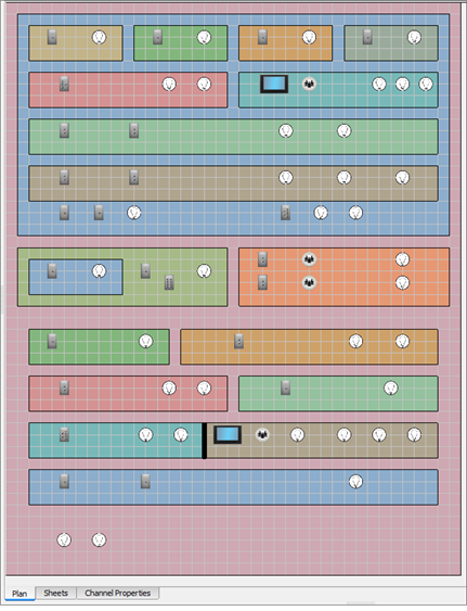
Design View
The Plan tab, as displayed in the Design view, displays the selected space with a grid pattern, which is helpful when laying out objects in the space. You can choose to snap new objects to the grid by enabling the snap to grid feature in the preferences dialog. Additionally, a background image can be imported and displayed behind the spaces, reference using background images.
Program/Simulate View
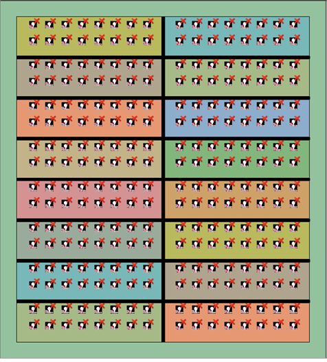
The Plan tab, as displayed in the Program/Simulate view, displays the all of the contents of a selected space in a colorful graphic simulation mode.
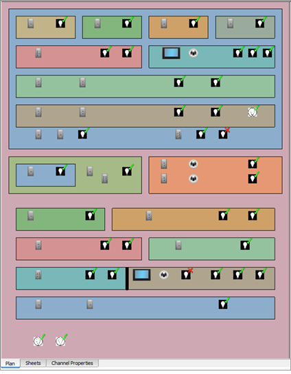
In simulation, objects such as channels, stations, walls, and Echo Expansion Bridges are displayed in simulation mode.
- Channels simulate both intensity level and output color (if any), as well as whether it is included in a selected preset, palette, or sequence, etc.
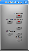
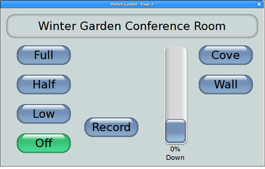
- Stations (including button, fader, BACnet buttons, touchscreens) simulate their control assignments including preset activation, channel fade, record, etc.
- Walls (partitions) simulate open and closed, allowing control scope to change depending on the wall state.
- Echo Expansion Bridges (EEB) display in simulation with up to 16 Echo spaces, each with up to 16 controllable Echo zones, with controllable walls that separate each Echo space.
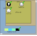
- Background images that have been imported in the Design view also display in the Program/Simulate view Plan tab. Alternatively, you can add a background image while in the Program/Simulate view.