 Reference Dimmer Properties Editor for configuration information.
Concert supports configuration of CEM3 control modules when installed in Sensor 3 dimmer racks (software version 1.2.2 and above) and FDX 3000 dimmer racks (software version 1.4.0 and above).
To configure a CEM3 device that is present in the configuration, double-click on the device icon in the Workspace or right-click on the device icon and select "Dimmer Properties" from the context menu. Alternatively, when operating in the Spreadsheet view, right-click on the device row and select "Dimmer Properties" from the context menu.
The Sensor 3 Rack (CEM3 Rack) dimmer property editor displays. Reference Dimmer Properties Editor for configuration information.
When adding a Sensor 3 or FDX 3000 dimmer rack with CEM3 control module to the configuration from the device library, drag and drop the device from the Power Controllers tab into the Workspace or Spreadsheet view. A "Setup Rack" dialog displays for specification of the rack details.
Note: When adding a device to the configuration from the device library using drag and drop, Concert by default adds the device's with its latest software version device package into the configuration. To specify a different software version for the device, drag the device from the device library, then press and hold the CTRL button before releasing the device into the Workspace or Spreadsheet view. A "Choose Device Version" dialog displays for specification of the installed device package to be used in the configuration.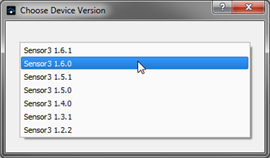
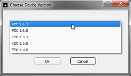
Only installed device packages display in the "Choose Device Version" dialog. To install a different device package for the device, reference the Component Manager.
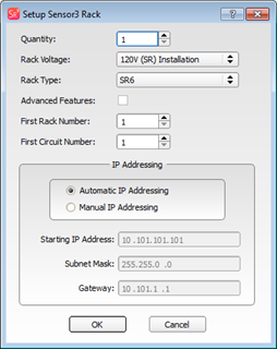
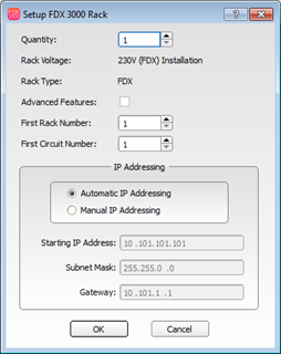
Provide rack information to complete the dialog and click [OK] to continue.
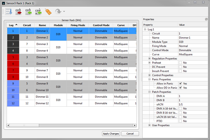
The Dimmer Properties Editor allows you to edit the configuration of dimmers or ranges of dimmers in your Sensor 3 rack and FDX rack. You can make changes in a variety of ways, including editing dimmers in the Table View, the Property Editor, using the Renumber Dimmers Dialog dialog, Import an ODS File or Import CEM+ configuration file.
VIDEO TUTORIAL: Click here to view a video tutorial showing how to use the "Dimmer Editor". To view the video tutorials, you must have installed an MP4 compatible video player, such as QuickTime.
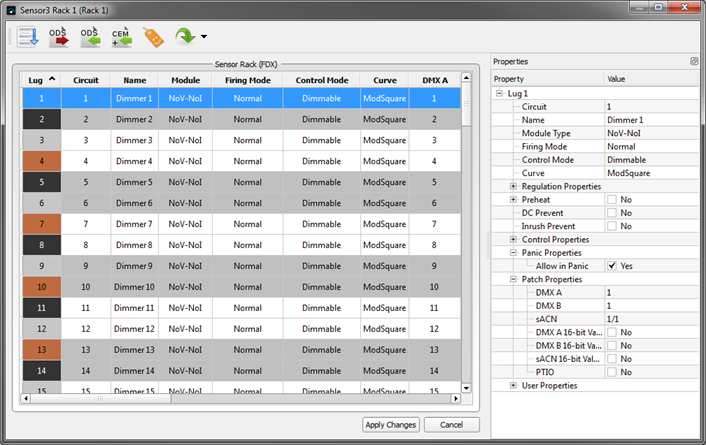
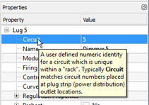
The most common properties for the Sensor 3 dimmers are shown in the table view of the selected rack as well as in the Property Editor. A summary of the purpose of each property can be viewed by hovering the mouse over the name of the property in the Property Editor . For complete information about the function of each property, refer to the Sensor 3 CEM3 User Manual. To edit any individual values in the table, simply click on the cell you wish to edit.
The following columns are shown in the table for edit:
Lug is the physical position of the circuit in the rack, starting at the top and working downwards.
Circuit is the logical reference number for the circuit (sometimes known as Dimmer Number). This is an editable, user assignable reference for the specific dimmer.
Name allows you to give each circuit a free-text name. The name will be shown in ETC Eos family consoles when Advanced dimmer feedback is enabled. Refer to the Sensor 3 CEM3 User Manual for information regarding Advanced Features.
Module defines the type of module that is or will be physically installed in the rack. ETC produces a wide range of dimmer modules for different applications, including dimming, relay and thru-power modules.
Firing Mode controls the manner in which the dimmer controls it's output.
The Control Mode of a dimmer controls the relationship between the control input (DMX, sACN) to the dimmer and it's output. Use this Control Mode property to set a dimmer to be switched, dimmable, smoothed, latchlock, always on or off.
Curve controls the "shape" of a dimmer's output. Sensor 3 dimming systems have a variety of curves available, as well as the ability to work with user defined curves. See "Custom Curve Editor" for more information.
The DMXA, DMXB and sACN columns contain the patch information of how the three possible control inputs to the rack relate to the dimmers. In US (SR) systems, columns are also available for Dimmer Doubled (DD) circuits.
User Data allows you to associate up to 8 free-text fields (similar to meta-data or meta-tags) with a dimmer for additional identification.
The Property Editor lists all properties of the selected dimmer(s). This editor allows you to view and alter every property of the dimmers in one simple interface. The Property Editor also allows you to edit multiple dimmers at once (unlike the table view which only allows editing of a single value at a time). Additional properties available in the Property Editor for the Sensor 3 rack with CEM3 control include:
For full details on the functions and available values for each feature, reference the CEM3 User Manual.
Spaces are logical divisions within a system that isolate station control (preset and sequence control) to the defined group of controllable outputs in that division. CEM3 supports separation of its controllable circuits into spaces and allows configuration of up to 16 presets per space. Each space can only have one active preset at a time.
CEM3 offers a Panic capability that complies with UL 924 Panic functionality. When a properly connected and enabled CEM3 has a panic “look” stored, when it receives a signal over the panic circuit it will automatically play the recorded look. Panic can be enabled when a maintained contact closure is properly wired to the back plane (for more information, see the data termination guide or installation guide that was supplied with the Sensor 3 rack).
When editing text fields in the Property Editor (such as the Name and User Data fields), you can use special character sequences to create helpful names. Each of the wild cards shown below will be automatically replaced by the appropriate value for all of the dimmers being edited.
| Wild card | Replaced With |
| %C | The current circuit's Circuit Number |
| %L | The current circuit's Lug Number |
| %R | The current Rack Number |
| %S | The current circuit's Space Number |
| %O | The current circuit's sACN address |
| %A | The current circuit's DMX A address |
| %B | The current circuit's DMX B address |
| %U | The current circuit's sACN universe value |
| %E | The current circuit's sACN absolute value |
| %M1 - %M8 | The current circuit's user data (value 1 thru 8) |
| %I | The index in the order in which these circuits were selected |
When you select a range of lugs and edit the circuit number or DMX or sACN address values, the value you enter will be used as a start address, and incremented as it is applied to each lug.
Tools are provided in the editor to provide access for dimmer renumbering, importing and exporting the rack configuration to an ODS file, import a CEM+ configuration, manage User Data Tags, and select another rack.
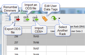
The Renumber dialog allows renumbering of the whole rack, or of a selection of dimmers within the rack. To access the Renumber dialog, click on the renumber dialog button at the top of the editor (![]() ).
).
VIDEO TUTORIAL: Click here to view an overview video tutorial showing how to use the "Renumber Sensor 3 Dimmers" dialog. To view the video tutorials, you must have installed an MP4 compatible video player, such as QuickTime.
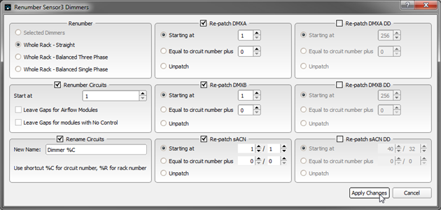
The Renumber dialog allows selection of what to renumber. This includes just selected dimmers, the whole rack with straight numbering, or the whole rack with balanced numbering.
The [Export ODS file] button ![]() allows you to export the data from your rack to an Open Document Spreadsheet (ODS) file format, which can be edited with popular spreadsheet software such as Microsoft Excel. This can be useful for compiling system data such as load schedules, and for editing and re-importing data using the ODS import function.
allows you to export the data from your rack to an Open Document Spreadsheet (ODS) file format, which can be edited with popular spreadsheet software such as Microsoft Excel. This can be useful for compiling system data such as load schedules, and for editing and re-importing data using the ODS import function.
VIDEO TUTORIAL: Click here to view an overview video tutorial showing how to use the "Export an ODS File" feature. To view the video tutorials, you must have installed an MP4 compatible video player, such as QuickTime.
Selecting the [Export ODS file] button displays a prompt for a directory to save the ODS file. A dialog displays when the data has successfully exported. An ODS file contains the following data:
The [Import an ODS file] button ![]() allows you to import data from an Open Document Spreadsheet (ODS) file created with spreadsheet software, or a file previously exported from Concert, or with ETC's Paradigm LightDesigner software.
allows you to import data from an Open Document Spreadsheet (ODS) file created with spreadsheet software, or a file previously exported from Concert, or with ETC's Paradigm LightDesigner software.
VIDEO TUTORIAL: Click here to view a video tutorial showing how to use the "Import an ODS File" feature. To view the video tutorials, you must have installed an MP4 compatible video player, such as QuickTime.
When you select to import an ODS file you will be first asked to select the file from a directory. Once selected, Concert ask how you would like to perform the import.
Once the data is imported, the changes are applied immediately and are shown in the table view of the editor.
The [Import CEM+] button ![]() , selectable only for Sensor 3 dimmer racks, allows you to import data from a Sensor+ system's (.RAK file), to simplify upgrades from CEM+ to CEM3. As a .RAK file contains data for multiple racks, when you select a file you will be prompted to select which rack's data you would like to import.
, selectable only for Sensor 3 dimmer racks, allows you to import data from a Sensor+ system's (.RAK file), to simplify upgrades from CEM+ to CEM3. As a .RAK file contains data for multiple racks, when you select a file you will be prompted to select which rack's data you would like to import.
VIDEO TUTORIAL: Click here to view a video tutorial showing how to use the "Import CEM+" feature. To view the video tutorials, you must have installed an MP4 compatible video player, such as QuickTime.
Tip: User Data, basically is data about data or could be better defined as the user defined purpose of the data. Each device offers the ability to include up to eight "User Data" fields that may be used to supply additional information about the device. User Data properties display in table view and in the Property Editor.
User Data Tags are provided as a way for user's to setup custom labels for User Data field as they are displayed in the Property Editor. By default, User Data Tags are labeled "User Data 1, User Data 2, etc., for each of the eight User Data fields that are available per object instance. User Data Tags could be considered or used as categories of User Data.
CEM3 features up to 8 user properties which you can use to classify circuits in the rack. The titles of these user properties are called user data tags, and may be edited by clicking on the [User Data Tags] button  in the editor toolbar. A Edit User Data Tags dialog is shown allowing editing of the user data tags from their default names, User Data 1 through User Data 8, in the rack.
VIDEO TUTORIAL: Click here to view an overview video tutorial showing how to use the "Edit User Data Tags" feature. To view the video tutorials, you must have installed an MP4 compatible video player, such as QuickTime.
When working in a system with multiple Sensor 3 racks, switch between the available racks in the logical system you are working in by clicking on the [Select Another Rack] button  . You will be shown a list of other racks in the selected system that you can switch to for configuration edit.
The CEM3 Load Monitoring viewer allows you to view and monitor the load currents of circuits in your dimming system. Load Monitoring is only available in racks with Sensor Advanced Features, or FDX racks. To view the Load Monitoring Editor, right-click on a Sensor 3 device icon in the Workspace and select "Load Monitoring" from the context menu. Alternatively, when operating in the Spreadsheet view, right-click on the device row and select "Load Monitoring" from the context menu. The Sensor 3 Load Monitoring viewer displays.
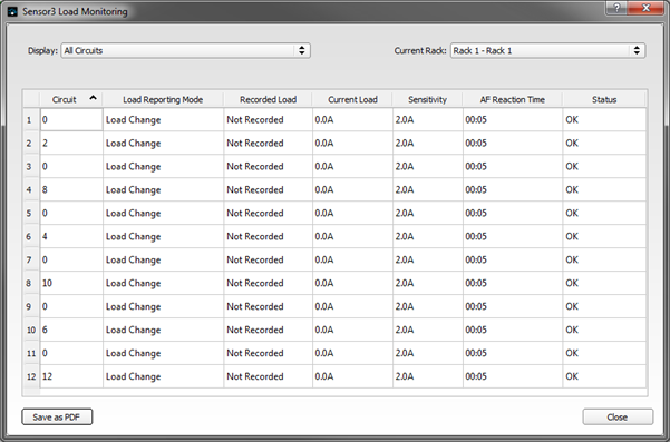
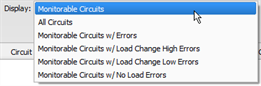
From this viewer, you can choose whether to display all circuits or to filter circuits based on their status and type.
You can also display circuits from any one rack or from all racks in your system .
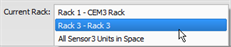
Note: When "All Sensor 3 Units in Space" is selected, you will be provided another filter selection box to specify the space. 
Tip: As with all tables throughout Concert, you can sort the table column data ascending or descending my clicking on the column header.
To save the displayed table data (as it is displayed) to a Portable Document Format (PDF), click the [Save as PDF] button on the bottom of the editor. The "Save As" dialog displays for confirmation of where the file should be saved.
The CEM3 provides the ability to specify and use custom dimmer curves and to provide a customized relationship between control input and voltage output of the selected dimmer. To edit custom curves, right-click on a Sensor 3 or FDX 3000 device icon in the Workspace and select "Custom Curves" from the context menu. Alternatively, when operating in the Spreadsheet view, right-click on the device row and select "Custom Curves" from the context menu. The Sensor 3 Custom Curve Editor displays.
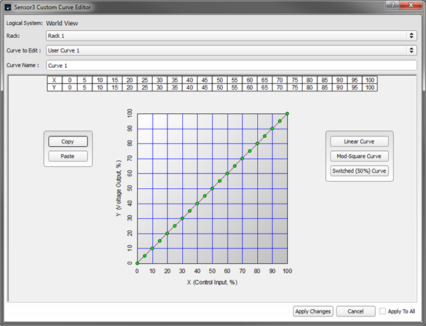
The custom curve editor allows you to select which rack in the logical system you want to modify curves for and which curve in the rack you want to edit. Each rack type supports five user definable curves.
Tip: Curves consist of 21 points in an X-Y graph where the X-axis represents the control input and the Y axis represents the voltage output of the rack.
To edit the selected curve, click on the point (green dot) you would like to edit and drag it to the new position on the graph, within the points boundaries. These boundaries will be apparent as you are manipulating each point. The dot color changes to red, indicating it is now the selected point and the [Apply Changes] button highlights to indicate an edit needs to be saved before closing the editor. See "Apply Changes"
Tip: You can also use the keyboard up, down, left and right arrows to move the selected point within its boundaries in the graph desired. With a point selected, pressing the Page Up and/or Page Down buttons changes the selected point within the curve.
If desired, you can initialize the curve to one of three preset types (Linear, Mod-Square or Switched) using the buttons on the right of the editor.
To copy and paste a custom curve between racks in the system, use the [Copy] and [Paste] buttons to the left of the graph in the editor.
Click the [Apply Changes] button to save the new edited data to the custom curve and to the selected rack. Click the "Apply To All" check box before clicking the [Apply Changes] button to apply the edited curve to all racks in the selected logical system.