Configuring the Unison Architectural Processor Application and Light Manager software version 1.65
|
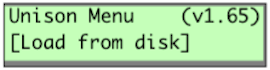
You configure the architectural processor for your system using the Unison (Architectural) menu. This menu lets you load the provided configuration, enter the Unison local control settings and other information used by the control processor. Each Unison control system has one architectural processor. ▼ If your system has an External Processing Rack, its control module will contain the architectural processor.
From the dimming rack▼ Access the Unison menu and scroll to [ARCH] with [▲] or [▼] and press [Enter]. The Unison menu will be displayed. From the external processing rack▼ Access the Unison menu and scroll to [ARCH] with [▲] or [▼] and press [Enter]. The Unison menu will be displayed. |
|||||||||
|
|
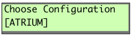
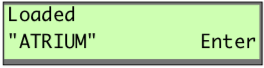
To load a Unison Light Manager configuration into the control processorThe Light Manager configuration provides system parameters such as number of rooms, number of zones in each room, number of presets and type and placement of stations.
|
||||||||
|
|
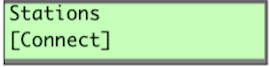
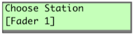
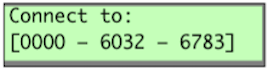
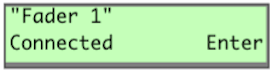
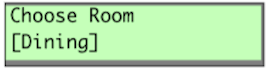
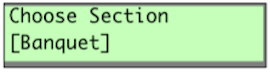
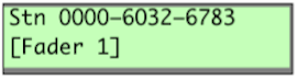
To bind control stations to the architectural processorBefore the architectural processor can identify signals from the wall stations, it has to link each control station to its ID number. This process is called "binding". Systems with a single station of a particular type (preset, fader, LCD) will automatically bind with the associated ID number.
|
||||||||
  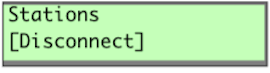    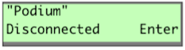 |
To unbind control stations (optional)When you need to remove or change a station, follow this procedure to unbind a control station from the architectural processor.
|
||||||||
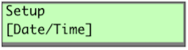
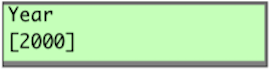
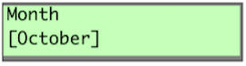
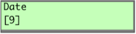
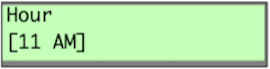
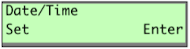
To enter the Date and Time local control settingsFollow this procedure to set the date and time in the astronomical time clock in the architectural processor. |
|||||||||
|
|
||||||||
 |
|
||||||||
 |
|
||||||||
 |
|
||||||||
 |
|
||||||||
 |
|
||||||||
 |
|
||||||||
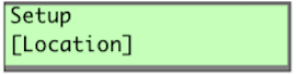
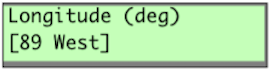
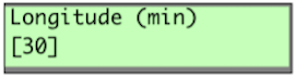
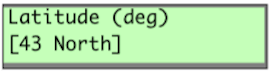
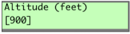
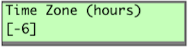
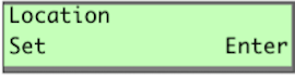
To enter your location settingsThe Location menu allows you to enter the installation latitude, longitude, elevation, and time zone into the Unison astronomical time clock. Refer to the Location Map on page 37. |
|||||||||
|
|
||||||||
 |
|
||||||||
 |
|
||||||||
 |
|
||||||||
 |
|
||||||||
 |
|
||||||||
 |
|
||||||||
 |
|
||||||||
 |
|
||||||||
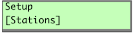
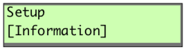
Working in the Setup menuAll of the following Setup menu options will allow you to access, change or set information about your Unison system. See "Appendix E: Architectural Menu Flow Chart" , for help on maneuvering through the menus. ▼ Stations ▼ Zones ▼ Presets ▼ Walls ▼ Load net backup ▼ Date/Time ▼ Location ▼ Format disk ▼ Processor/Address
▼ Information |
|||||||||
 |
Working in the Setup Information MenuThe following Setup menu options will allow you to access, change or set information in the Setup Information menu. |
||||||||
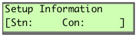 |
▼ Number of stations and number of connected stations in the configuration. "Stn:" indicates number of stations in the Light Manager configuration. "Con:" indicates number of bound physical station on the Union Link Power (ULP) network. | ||||||||
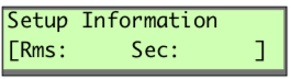 |
▼ Number of rooms and sections in the configuration | ||||||||
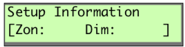 |
▼ Number of zones and dimmers in the configuration | ||||||||
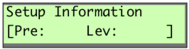 |
▼ Number or presets and levels in the configuration | ||||||||
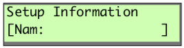 |
▼ Job or configuration name | ||||||||
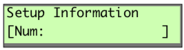 |
▼ Job or configuration number | ||||||||
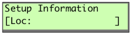 |
▼ Job location | ||||||||
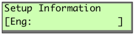 |
▼ Job engineer | ||||||||
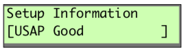 |
▼ Number of good Unison Serial Access Protocol (USAP) commands received | ||||||||
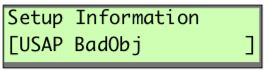 |
▼ Number of USAP commands with bad objects | ||||||||
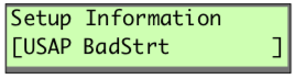 |
▼ Number of premature start bit | ||||||||
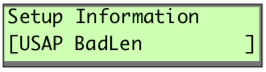 |
▼ Number of commands that were the wrong length | ||||||||
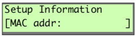 |
▼ MAC address in Hex | ||||||||
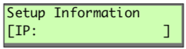 |
▼ IP address | ||||||||
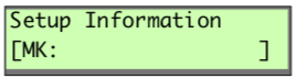 |
▼ IP Mask number | ||||||||
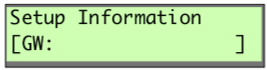 |
▼ IP Gateway number | ||||||||
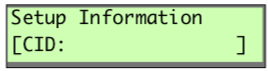 |
▼ CID number | ||||||||
Working in the Diagnostics menuAs with the Setup menu, the Diagnostics menu will allow you to access advanced information about your configuration. ▼ Run Macro ▼ Stop Macro ▼ Dimmers
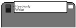
▼ Stations ▼ All Zones Off ▼ Initialize Flash ▼ Reset Stations ▼ Send Object Model The write-enable tab must be in the "Write" position to format a disk |
|||||||||
|
The write-enable tab must be in the "Write" position to format a disk |
To format floppy disk (optional)If you have an unformated double-sided, high-density disk, you can format it in the Control Module’s disk drive.
▼ "Disk Formatted" displays if formatting is successful. |
||||||||
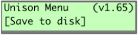
To save the installed configurationYou should keep a copy of your installed Unison configuration to another 1.44 MB IBM DS HD format 3.5" floppy disk (not your original configuration disk.) Saving the installed configuration records binding and location information entered while binding stations and setting up the system.
|