Fluorescent Dimming How Fluorescent Fixtures Work
Fluorescent Dimming How Fluorescent Fixtures Work
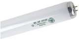 A fluorescent lamp works much the way a neon tube does. There are electrodes at each end that are heated in order to reduce the amount of strike current required to excite the gas in the tube. Once the tube is excited, the electrodes continue to remain heated due to current transfer, but the voltage required to maintain the gas excitation drops down significantly from the strike voltage.
The inside of the lamp is coated with a phosphor mix that illuminates when UV radiation comes in contact with the glass. Since light is not a direct result of filament glow, fluorescent lamps are inherently more efficient than incandescents.
Magnetic and electronic ballasts are both used with fluorescent lamps. Electronic ballasts are preferred since they are lighter in weight, emit less heat, and use high frequency voltage waveforms to eliminate visible lamp flicker. Electronic ballasts usually operate in the 32kHz range for example, rather than the 120Hz used by magnetics. This on occasion has been known to cause other problems such as increased line harmonics and interference with infrared control devices, but the pros outweigh the cons.
Compact Fluorescents
Compact fluorescents refer to a fluorescent lamp that has its size reduced either by being coiled or folded to produce the effect of a long tube in a small space.
There are two types of compact fluorescent :
Integrated 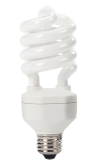
The ballast is built into the lamp base. Such types can be used as a direct replacement for standard Edison Screw or Bayonet lamps. However, dimming performance is poor. Even "Dimmable" versions of the integrated CFL do not provide smooth dimming through a wide range.
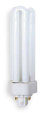 Non-Integrated
Non-integrated Compact Fluorescents have a separate ballast, similar to a standard fluorescent tube.
Dimmable ballasts are available for non-integrated compact fluorescents, and do provide reasonable dimming performance.
Compact fluorescents must be burned in at full for 100 hours before dimming (see additional info below). Failure to do so will lead to blackening and premature failure of the lamp.
How fluorescent fixtures are dimmed
It is important to realise when dimming fluorescents that it is impossible to create a smooth transition between "off" and a level. Because light is generated by a discharge through gas, similar to an arc lamp or neon tube, there will always be a "jump" in light level when the tube initially strikes. The brightness to which the level "jumps" is determined by the ballast - see the section below on dimmable percentages. Always remember when dimming fluorescents, performance will not be the same as a traditional, dimmable, incandescent lamp.
Fluorescent fixtures are dimmed using a special dimmable ballast. This is because standard ballasts typically do not have the ability to maintain electrode heat to the degree required for proper gas excitation when input voltage is varied. While magnetic dimmable ballasts do exist, almost all dimmable ballasts these days are electronic.
Electronic ballasts vary the frequency at which they run the lamps without changing the electrode voltage and are therefore able to get a much wider range of dimming. Where magnetics were doing really good to get lamp output down to 20-40%, electronic ballasts can dim down to 1% on some models.
About the different dimmable ballasts
Ballasts are commonly referred to by the number of wires that feed them. There are three different ballast types that are available in the US(110V 60Hz) market. Ballasts come in 2-wire, 3-wire, and 4-wire models. 2 wire ballasts are extremely uncommon in Europe (the lower frequency means they do not operate correctly) so virtually all dimmable fluorescents are 3- or 4-Wire.
2-Wire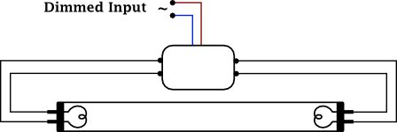
These are very common ballasts and the easiest to install. They require a dimmed hot and a neutral (ground is understood) and are available in 5% dimmed models from such companies as Lutronand Advance (Philips). They are installed and controlled on one dimmer just as you would an incandescent source except that a bottom-end threshold is set. This setting keeps the lamps from running below their recommended voltage, preventing premature failure of both lamps and ballasts.
2-wire ballasts are made in both forward phase and reverse phase variants. To dim a reverse phase ballast you will need to use a reverse phase dimmer module such as ETC's ELV10 dimmer in a compatible dimmer rack.
3-Wire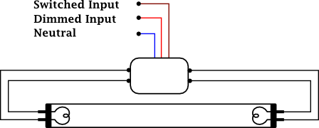
These ballasts are also common and are usually quite inexpensive. However, they use two dimmers for control and power as they require a dimmed hot, a switched hot, and a neutral (ground is understood). Advance and Lutron make them in 1%, 5%, and 10% models. A threshold like the 2-wire models is used and at the point one dimmer goes to full (non-dim) and the other begins its fade to full. The dimmer module is special since by code it must have only one breaker for both outputs.
4-Wire
4 Wire Ballasts use a hot (non-dim) and neutral (ground is understood) plus two low-voltage conductors for 0-10vdc control (analog) or DSI or DALI control protocols (digital). They are available in 5% and 10% control models. Again, a threshold is used to set the bottom power and control voltage. Use standard dimmer modules in conjunction with a 0-10vdc control card such as the FLO board in Unison dimming. Please note that current is sourced by the ballast and sinked by the FLO board so a standard D/A may not work. There will be more on this later.
About the different dimmable percentages
There are always lots of questions surrounding the dimming percentages manufacturers publish in regards to ballasts. The percentages are based on light output measured with a light meter. The human eye does not perceive light increase linearly but rather as a close function of "square law," yet light meters do use a linear scale. Therefore, when looking at the minimum light level output by a fluorescent fixture, the eye will see more light than the percentage touted. Here is a chart to give you a better comparison between advertised or measured versus perceived light.
| Ballast type (what the manufacturers market) | Measured light (what is seen by a meter) | Perceived light (what is seen by you) |
|---|---|---|
| 1% | 1% | 10% |
| 5% | 5% | 22.4% |
| 10% | 10% | 32% |
| 20% | 20% | 46% |
The 5% ballast is the most prevalent of all the ballast types. It is very common for a system purchaser to not understand why their fluorescent lights do not dim down to 5%. Please help them see why 5% means light output as opposed to perceived light or control level.
Important installation tips
- It is a good idea to "season" the lamps for 100 hours prior to being dimmed. Although it is no longer required by lamp or ballast manufacturers, it does tend to improve performance. It is recommended that a few spare fixtures be purchased and installed in the storage room to provide a lamp burn-in area. The one exception to the above is compact fluorescent lamps which absolutely must be burned in for 100 hours before dimming. Failure to do so will result in blackening and premature lamp failure.
- Make sure the fixtures are adequately grounded. The lamp must be in close proximity to a metal ground plane in order to reduce flicker and increase lamp life. The distance should be 0.5" within +/- 0.25".
- Do not mix ballast or lamp types on the same circuit. Contrary to popular belief, ballasts can interact with each other on the same circuit. The same is true for lamps as they do fire differently and should never be mixed within a fixture.
- Please use the following chart to determine the correct ETC dimmer module for your ballasts:
| 2-wire (Forward Phase) | 2-wire (Reverse Phase) | 3-wire | 4-wire | |
|---|---|---|---|---|
| 120VAC (USA) | D15 / D20 | ELV10 | D15F / D20F | D15 / D20 |
| 230VAC (CE, Europe) | ED15 / Matrix iSCR | Matrix iSine | ED15AFRF/ Matrix Fluorescent | ED15 / ER15 |
| 277VAC (USA) | AD20 | - | AD20F | AD20 |
ETC in the past produced some forward phase modules that handled low loads better, known as the L10 (110V) and AL5 (277V). The L series used MOSFET and IGBT technology to more accurately dim low wattage loads. Due to dimming control improvements in the Unison DRd enclosure and Sensor CEM+/ CEM3 control modules, these modules were discontinued and are no longer needed.
How to tune an ETC Legacy Unison system for dimming fluorescents
When configuring the dimming engine on a Unison processor, please verify that you select the correct module type and the appropriate load type. When you select fluorescent, you will be asked what percentage ballast you are using. The curve and threshold will be set automatically. It is suggested that you set the % level a little above the required setting form the ballast manufacturer, by doing this it will avoid flickering in the future.
How to tune an ETC Sensor system for dimming fluorescents
Sensor is quite a bit different in how it should be set for proper fluorescent dimming. You must first set the curve you wish to use. Most people select Linear, but there is a Modified Linear as well that has a softer bottom end of the curve. After that, set the Threshold to about 60% and measure the RMS voltage output for the dimmer at its minimum setting. You are looking for voltage to be 0.47 times the incoming line voltage. If 60% is not correct, select another Threshold that is closer to the desired output and verify with the meter. With this type of setting (let's assume 60% Threshold) your fader will have a large area of travel (between 0 and 59%) where nothing will happen.
Other information
On Legacy Unison systems, you can set the Zone to have a minimum level of 60, maximum of full and select the box labeled, "Use zero as off." This will give your wall station fader complete control of the ballast across the entire range of the fader and still turn off at the bottom of the fader travel. This is a very nice solution.
When running ballasts from a DMX control console, take time to program a profile to emulate the Unison programming, or record all your cues with those affected channels between 59 and full. That way a timed fade will still operate with all fluorescent and non-fluorescent channels in parallel.
Troubleshooting dimmed fluorescents
|
1. Lamps are at different levels on different ballasts |
|
|
2. Lamps have blackened ends |
|
|
3. Lamps flicker or flash at low levels only |
|
|
4. Lamps flicker or flash at all levels |
|
| 5. Lamps come on at full at low-end of control and do not dim. |
|
|
6. Lamps do not dim to the lowest level |
|
What ballasts not to use with ETC equipment
Make sure you use the correct module (ELV10) when dimming reverse-phase control ballasts. All other Sensor and Unison dimmer modules provide forward-phase control. The use of ballasts not intended for these systems will cause a variety of problems and will not dim correctly. The most common manufacturer of these ballasts is ESI. Lightolier makes a converter box in one and two-channel models to adapt the forward-phase control signal to reverse-phase control, but the cost is quite significant. Most dimmable ballasts made today are electronic and are easy to work with. However, as people are retrofitting older facilities, dimmable magnetic ballasts are being used as well. Most magnetics can be dimmed, but as always, if there is any doubt, test it first. (Contact applications engineering with questions) Magnetic ballasts must be thermally protected to prevent non-sinusoidal waveforms from causing overheating.
Fluorescent Lamp and Ballast Types
There are a variety of naming standards for fluorescent lamps; here is a quick summary
Diameter
A T-prefixed number indicates the diameter of the tube.
|
T-Number |
Diameter |
|---|---|
|
T12 |
1.5inches |
|
T8 |
1.0inches |
|
T5 |
0.5inches |
Length & Wattage
The length and wattage of the tube are interdependent.
|
Wattage |
Length |
|---|---|
|
40W |
48 inches (1220mm) |
|
30W |
36 inches (910mm) |
|
20W |
24 inches (610mm) |
|
13W |
21 inches (530mm) |
|
15W |
18 inches (460mm) |
|
14W |
15 inches (380mm) |
|
8W |
12 inches (300mm) |
|
6W |
8 inches (230mm) |
|
4W |
6 inches (150mm) |